2-Point Source
Interference Patterns
Changing Separation
Distance
A GIF Animation
Wave interference is a phenomenon which occurs when two waves
meet while traveling along the same medium. Wave interference can be
constructive or destructive. Constructive interference occurs
wherever a crest of one wave meets a crest of a second wave (or when
a trough of two waves meet). When a crest meets a crest, the
resultant displacement of the medium at that location is larger than
the displacement of either of the two individual wave crests. A new
and larger wave is constructed. Destructive interference occurs
wherever a crest of one wave meets a trough of a second wave. When a
crest meets a trough, the two individual waves combine to produce a
new wave which has a resultant displacement which is smaller than the
displacement of the larger wave. That is, the two waves combine to
either partially or completely destroy each other.
The interference of two sets of circular waves with the same
frequency and the same amplitude results in a standing wave pattern.
These standing wave patterns are known as two-point source
interference patterns since they result from the interference of
circular waves from two sources. A standing wave pattern is a wave
pattern in which there are points along the medium which appear to be
standing still. These points are called nodes - points of no
displacement. Nodes are produced when destructive interference
always occurs at the same location; a crest and a trough with the
same magnitude of displacement interfere to provide complete
destructive interference and no resulting displacement of the medium.
In a standing wave pattern, the nodes are separated by anti-nodes.
Anti-nodes are points along the medium which oscillate between a
large negative displacement and a large positive displacement.
Anti-nodes result from the constructive interference of two waves. A
crest meets a crest to produce a large positive displacement; and
moments later, a trough meets a trough to produce a large negative
displacment.
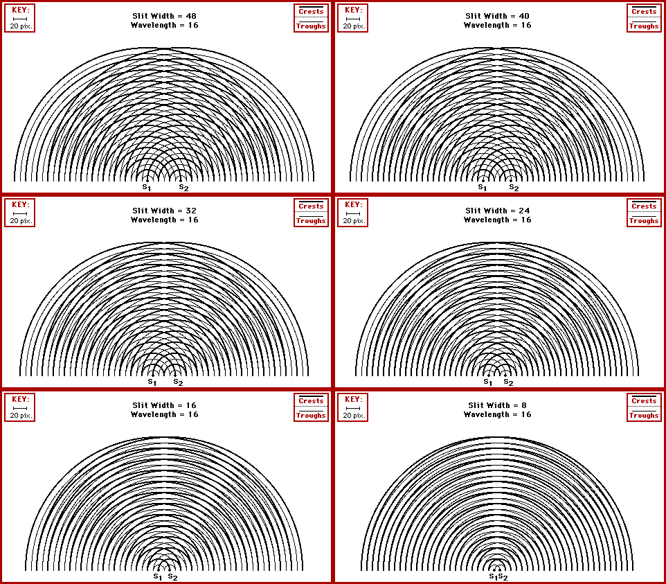
The diagram below shows several two-point source interference
patterns. The crests of each wave is denoted by a thick line while
the troughs are denoted by a thin line. Subsequently, the anti-nodes
are the points where either the thick lines are meeting or the thin
lines are meeting. The nodes are the points where a thick line meets
a thin line.

Observe that the nodes of the pattern are oriented along lines -
known as nodal lines. Similarly, the anti-nodes in the pattern are
also oriented along lines - known as anti-nodal lines. The spacing
between these lines is related to the distance between the sources.
The two sources are represented by S1 and S2 in
the diagram. As the sources move closer together, the spacing
between the nodal lines and the anti-nodal lines increases. That
is, the nodal and anti-nodal lines spread farther apart as the
sources come closer together.
In 1801, Thomas Young used a two-point source interference
pattern to measure the wavelength of light. Young passed
monochromatic light through two slits (acting as the sources) and
upon a screen some distance away. The projection of the nodal and
anti-nodal lines on the screen produced an alternating pattern of
dark and bright lines. Young used wave principles to establish that
the wavelength of light could be mathematically related to the
separation distance, the distance to the screen, and the distance
between anti-nodal lines (bright spots). Young made accurate
measurements and determined the wavelength of light.
For more information on physical descriptions of waves,
visit
The
Physics Classroom. Specific information is available there on the
following topics:
Other animations can be seen at the
Multimedia
Physics Studios. Other useful resources regarding the physics of
motion and waves is available through the
Glenbrook
South Physics Home Page.
This page was created by
Tom
Henderson of
Glenbrook South
High School.
Comments and suggestions can be sent by e-mail to
Tom
Henderson.
This page last updated on 8/18/98.
